シェーダで図形の描画
距離関数
シェーダを用いて図形を描画するには、距離関数が必要となります。この距離関数は図形ごとに異なる関数となります。図形ごとの距離関数とその関数によって描画される図形は以下の通りです。
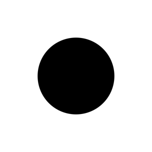
円
円の距離関数です。radiusによって円の大きさを変更できます。。
float circle(float2 p, float radius){
	return length(p) - radius;
}
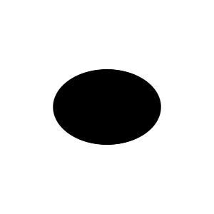
楕円
楕円の距離関数です。rは縦横の幅をsizeで大きさを変更できます。
float ellipse(float2 p, float2 r, float size){
	return length(p / r) - size;
}
四角形
四角形の距離関数です。sizeによって縦横の幅を変更できます。
float rectangle(float2 p, float2 size){
	return max(abs(p.x) - size.x, abs(p.y) - size.y);
}
ひし形
ひし形の距離関数です。sizeによって大きさを変更できます。
float rhombus(float2 p){
	return abs(p.x) + abs(p.y) - size;
}
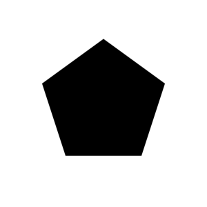
多角形
多角形の距離関数です。nは辺の数を、sizeで大きさを変更できます。
float polygon(float2 p, int n, float size){
	float a = atan2(p.x, p.y) + PI;
	float r = 2 * PI / n;
	return cos(floor(0.5 + a / r) * r - a) * length(p) - size;
}
円環
円環の距離関数です。sizeで大きさを、wで円環の太さを変更できます。
float ring(float2 p, float size, float w){
	return abs(length(p) - size) + w;
}
星
星の距離関数です。\(n=5,t=0.5 \) とすると下画像のような星となります。また、sizeで大きさを変更できます。
float star(float2 p, int n, float t, float size){
	float a = 2 * PI / float(n) / 2;
	float c = cos(a);
	float s = sin(a);
	float2 r = mul(p, float2x2(c, -s, s, c));
	return (polygon(p, n, size) - polygon(r, n, size) * t) / (1 - t);
}
ハート
glsl 色々なハートの描き方で紹介されている方法を少し変更したコードです。
また、sizeで大きさを変更できます。
float heart(float2 p, float size){
	p.x = 1.2 * p.x - sign(p.x) * p.y * 0.55;
	return length(p) - size;
}
楕円を利用して作成したハートです。sizeで大きさを変更できます。
float heart(float2 p, float size){
	float angle = PI / 180 * - 48;
	p.x = abs(p.x);
	p = float2(p.x * cos(angle) - p.y * sin(angle), p.x * sin(angle) +  p.y * cos(angle));
	return ellipse(p, float2(0.9, 0.5), size);

}
図形の描画
以上の距離関数を利用して図形を描画するコードは以下の通りです。uv座標の値は0~1なので、frac(i.uv) * 2 – 1によって-1~1へ変更しています。また、smoothstepを使用することで境界を滑らかにしています。
float circle(float2 p, float radius){
	return length(p) - radius;
}

fixed4 frag (v2f i) : SV_Target
{
	float2 f_st = frac(i.uv) * 2 - 1;

	float ci = circle(f_st, -0.3);

	fixed4 col = smoothstep(0.5, 0.51, ci);
	return col;
}
移動
座標に任意の値を加減算すれば 図形の移動ができます。 下記コードでは四角形を中心から一定の距離ずらしています。
fixed4 frag (v2f i) : SV_Target
{
	float2 f_st = frac(i.uv) * 2 - 1;

	f_st += float2(0.2, 0.3);
	float rect = rectangle(f_st, float2(-0.38, -0.38));

	fixed4 col = smoothstep(0.5, 0.51, rect);
	return col;
}
さらに、下記コードのように\(\sin\)と_Time.yを使用すると図形を往復させることができます。
fixed4 frag (v2f i) : SV_Target
{
	float2 f_st = frac(i.uv) * 2 - 1;

	f_st.x += 0.8 * sin(_Time.y * 1.3);
	float rect = rectangle(f_st, float2(-0.38, -0.38));

	fixed4 col = smoothstep(0.5, 0.51, rect);
	return col;
}![]()
回転
図形の回転
二次元の回転は以下の式で求めることができます。
$$ \begin{equation} \begin{bmatrix} x’\\ y’ \end{bmatrix} = \begin{bmatrix} \cos\theta&-\sin\theta\\ \sin\theta&\cos\theta \end{bmatrix} \begin{bmatrix} x\\ y \end{bmatrix} \end{equation} $$この式によって座標を回転させると、図形を回転させることができます。四角形を回転させるコードは以下の通りです。
float2 rotation(float2 p, float theta){
	return float2((p.x) * cos(theta) - p.y * sin(theta), p.x * sin(theta) +  p.y * cos(theta));
}

fixed4 frag (v2f i) : SV_Target
{
	float2 f_st = frac(i.uv) * 2 - 1;

	float theta = _Time.y * 5;

	f_st.x += 0.8 * sin(_Time.y * 1.3);
	f_st = rotation(f_st, theta);

	float rect = rectangle(f_st, 0);

	fixed4 col = smoothstep(0.1, 0.11, rect);
	return col;
}
座標を回転する前に座標に値を加減算することで、図形の位置を変更することができます。実行結果は以下の通りです。
図形の位置を回転
図形自身を回転させずに、ある点回りに図形を回転させる方法です。単純に\(\sin\)と\(\cos\)を座標に加減算するだけで回転させることができます。コードは以下の通りです。
fixed4 frag (v2f i) : SV_Target
{
	float2 f_st = frac(i.uv) * 2 - 1;

	float theta = _Time.y;

	float2 rad = float2(0.2, 0.2);
	f_st += float2(rad.x * sin(theta / rad.x), rad.y * cos(theta / rad.y));

	float rect = rectangle(f_st, 0);

	fixed4 col = smoothstep(0.1, 0.11, rect);
	return col;
}
_Time.yにかける値により回転速度を調整することができます。また、radは回転半径です。\(\sin\)と\(\cos\)内のthetaを回転半径で除算することによって、回転半径によって速度が変わらないようにしています。そして、座標に\(\sin\)と\(\cos\)を加減算した後に、さらに値を加減算することで、回転中心を変えることができます。上記コードの実行結果は以下の通りです。
回転行列による図形位置の回転
回転行列による図形位置の回転のコードは以下の通りです。
float2 rotation(float2 p, float theta){
	return float2((p.x) * cos(theta) - p.y * sin(theta), p.x * sin(theta) +  p.y * cos(theta));
}

fixed4 frag (v2f i) : SV_Target
{
	float2 f_st = frac(i.uv) * 2 - 1;

	float theta = _Time.y * 2;

	f_st = rotation(f_st, theta_1 * 2);
	f_st.x += 0.58;

	float rect = rectangle(f_st, 0);

	fixed4 col = smoothstep(0.1, 0.11, rect);
	return col;
}
このコードによって回転させると、回転角度に伴って図形自身も回転します。実行結果は以下のようになります。
図形の繰り返し表示
uv座標に定数を掛けることで同じ図形を等間隔に複数表示することができます。コードは以下の通りです。
fixed4 frag (v2f i) : SV_Target
{
	float size = 3;
	float2 f_st = frac(i.uv * size) * 2 - 1;

	float ci = circle(f_st, 0);

	fixed4 col = smoothstep(0.5, 0.52, ci);
	return col;
}
sizeは表示する図形の数となります。実行結果は以下の通りです。
モーフィング
図形ごとに距離関数によって値を求め、それらを線形補間することで、ある図形から他の図形へと自然に変形させることができます。丸から四角へ変形した後に四角から丸への変形を繰り返すコードは以下のようになります。
fixed4 frag (v2f i) : SV_Target
{
	float2 f_st = frac(i.uv) * 2 - 1;

	float ci = circle(f_st, 0);
	float rect = rectangle(f_st, float2(0, 0));

	float time = (sin(_Time.y * 1.5) + 1) * 0.5;
	float morph = lerp(ci, rect, time);

	fixed4 col = smoothstep(0.5, 0.51, morph);
	return col;
}
このコードを実行した結果は以下の通りです。

組み合わせ
図形を中心回りに回転させ、その円上を中心として、さらに回転させた図形を回転させつつモーフィングを行うコードです。
float circle(float2 p, float radius){
	return length(p) - radius;
}

float rectangle(float2 p, float2 size){
	return max(abs(p.x) - size.x, abs(p.y) - size.y);
}

float2 rotation_1(float2 p, float theta){
	return float2((p.x) * cos(theta) - p.y * sin(theta), p.x * sin(theta) +  p.y * cos(theta));
}

float2 rotation_2(float2 p, float theta, float rad){
	return p + float2(rad * sin(theta / rad), rad * cos(theta / rad));
}

fixed4 frag (v2f i) : SV_Target
{
	float2 f_st = frac(i.uv) * 2 - 1;
	float theta_1 = _Time.y * 0.2;
	float theta_2 = _Time.y;
	float theta_3 = _Time.y * 5;

	f_st = rotation_2(f_st, theta_1, 0.65);
	f_st = rotation_2(f_st, theta_2, 0.2);
	f_st = rotation_1(f_st, theta_3);

	float ci = circle(f_st, 0);
	float rect = rectangle(f_st, float2(0, 0));
	float time = (sin(_Time.y * 1.5) + 1) * 0.5;
	float morph = lerp(ci, rect, time);

	fixed4 col = smoothstep(0.1, 0.11, morph);
	return col;
}
実行結果は以下の通りです。
四角形を複数の円へ変形するコードです。
float circle(float2 p, float radius){
	return length(p) - radius;
}

float rectangle(float2 p, float2 size){
	return max(abs(p.x) - size.x, abs(p.y) - size.y);
}

fixed4 frag (v2f i) : SV_Target
{
	float2 st = i.uv;
	float2 f_st = frac(st) * 2 - 1;

	float2 ci_st = frac(st) * 4;
	float2 i_ci_st = floor(ci_st);
	float2 f_ci_st = frac(ci_st) * 0.5 - 0.25;

	f_ci_st = abs(f_ci_st) + (abs(i_ci_st - 1.5) - 0.5);
	float2 ci = circle(f_ci_st, -0.3);

	float2 rect = rectangle(f_st, -0.05);

	float t = sin(_Time.x * 20) * 0.5 + 0.5;
	float morph = lerp(ci, rect, t);

	fixed4 col= smoothstep(0.5, 0.51, morph);
	return col;
}
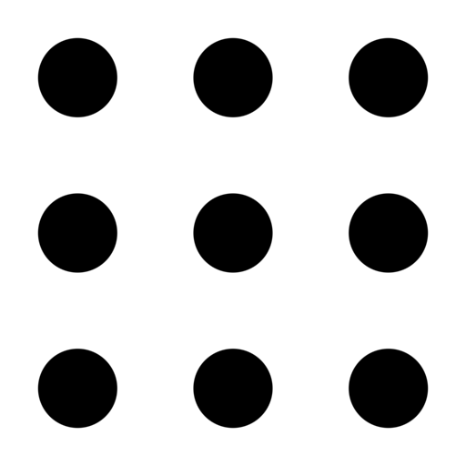
円はuv値に4を掛けているので4×4で16個表示されますが、
f_ci_st = abs(f_ci_st) + (abs(i_ci_st - 1.5) - 0.5);によって中央の4個のみ表示されるように処理をしています。実行結果は以下の通りです。
参考ページ
-
前の記事

素材追加(2019/3/29更新) 2019.03.29
-
次の記事
シェーダでトランジション(ノイズ) 2019.05.01